
Control Valve with Positioner | 4Matic Valve Automation
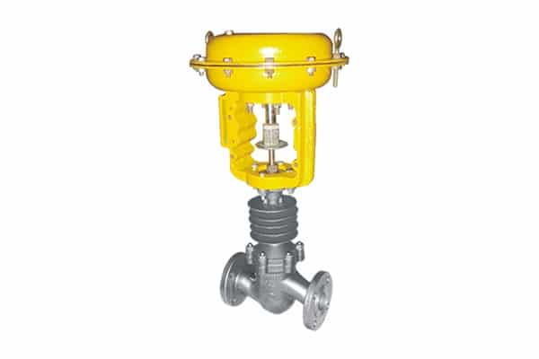
Positioner Control Valve is a type of valve that ensures maximum accuracy and efficiency in flow control applications by ensuring that the valve reaches its optimum position based on the need of the process application. The valve constantly compares the input signal and the position of the valve and fine tunes it for smooth, reliable and efficient operation.
These valves are suitable for use with both rotary and linear actuator and can therefore be used in a variety of process control applications including process automation, chemical industries, oil and gas, power and water treatment industries.
Made from high quality materials and using superior engineering standards, these valves ensure maximum reliability and efficient operation in industrial conditions.
- Precise valve position for accurate flow control
- Compatible with rotary and linear actuators alike
- Double acting or spring return types available
- Quick response time for enhanced stability
- High positioning accuracy with low hysteresis
- Durable and corrosion-resistant construction
- Simple to install, calibrate, and maintain
- Designed for use in tough industrial environments
- Minimal air usage for efficient performance
- Long-lasting and dependable performance
- Petroleum and Natural Gas Refining
- Chemical and Petrochemical Plants
- Electric Power Generation
- Water and Wastewater Treatment
- Pharmaceutical Manufacturing
- Food and Beverage Industry
- Paper and Pulp Industry
- Metal and Steel Industry
- Refineries
- Automation Process Systems
- Valve Type: Pneumatic, Electric, or Hydraulic Control Valve with Positioner
- Signal Range: 4–20 mA, Pneumatic (3–15 psi), or Digital Communication (HART, Fieldbus, etc.)
- Valve Size: Available in small to large sizes based on application requirements
- Pressure Class: ANSI Class 150 to Class 2500 (or equivalent)
- Temperature Range: Suitable for low to high-temperature process applications
- Materials of Construction: Carbon Steel, Stainless Steel, Alloy Steel, and corrosion-resistant materials
- Trim Material: Stainless Steel, Alloy, and specialized materials
- Actuator Type: Pneumatic Single Acting, Double Acting, Electric, or Hydraulic Actuator
- Position Accuracy: High positioning accuracy for precise control
- Flow Characteristics: Linear, Equal Percentage, or Quick Opening
- Communication Protocols: HART, Foundation Fieldbus, PROFIBUS, and digital communication capabilities
FAQs – Positioner Control Valve
A positioner control valve is a control valve fitted with a positioner to ensure that the valve stem or shaft moves to the precise position required by the control system. Its function is to increase the accuracy of the valve operation through changing the actuator pressure depending on the position of the valve.
The valve positioner works by receiving the control signal from the automation system and comparing it with the position of the valve. In case of a discrepancy, it adjusts the actuator pressure to get the required valve position.
The positioner is used in control valves to improve positioning accuracy, offset friction and pressure force, and achieve faster response in challenging processes.
There are three main types of control valve positioners; they include pneumatic positioners, electro-pneumatic (I/P) positioners, and digital valve positioners.